
Categories
-
0 Glass-Filled Materials in Injection Moulding
- Projects
- by Ben West
- 21-08-2026
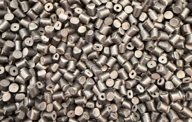
0.00 of 0 votesCase Study: Glass-Filled Materials in Injection Moulding Understanding Glass Bead and Glass Fibre Reinforced Plastics At Kent Precision Products Ltd, we regularly work with engineering polymers where standard unfilled plastics cannot provide the mechanical strength, stiffness, dimensional stability or temperature performance required by the finished component. One common solution is the use of glass-filled thermoplastics. These materials combine a base polymer—such as Nylon (PA), PBT, PP or other engineering plastics—with glass reinforcement. Two common reinforcement systems are: Glass Fibre Filled – short glass fibres are incorporated into the polymer to significantly increase strength and stiffness. Glass Bead Filled – small spherical glass particles are incorporated into the polymer, typically to improve dimensional stability, rigidity and control shrinkage while generally producing less directional behaviour than fibres. Although both materials contain glass, they can behave very differently during injection moulding. Understanding these differences is particularly important when designing the mould tool and, crucially, deciding where and how the component is gated. Why Use Glass Fibre? Glass fibre reinforced polymers are widely used where a component needs to withstand higher mechanical loads than an equivalent unfilled polymer. Depending on the polymer and percentage of reinforcement, glass fibre can provide: Increased tensile strength Increased stiffness Improved resistance to deformation Better performance at elevated temperatures Reduced overall moulding shrinkage Improved creep resistance Greater dimensional stability under load Common grades may contain 15%, 20%, 30%, 40% or even 50% glass fibre. However, adding glass fibre also changes the way the material behaves as it flows through the mould. Fibre Orientation – Why Gate Direction Matters One of the most important considerations when moulding glass fibre reinforced materials is fibre orientation. As molten material travels through the runner, gate and mould cavity, the glass fibres tend to align with the direction of material flow. This means that the finished component can have different mechanical and shrinkage properties depending on the direction in which it is measured. The fibres tend to align along the flow path. This can be extremely useful when it is deliberately engineered into the component—but problematic when it is not considered during tool design. The Importance of Gate Position Gate location should never be considered simply as the easiest place to introduce plastic into the component. With glass-filled materials, the gate can influence the final mechanical behaviour of the component. Imagine a long structural moulding designed to carry a load along its length. If the gate is positioned so that the material flows along the length of the component, a significant proportion of the glass fibres can become orientated in that direction. This can provide greater strength and stiffness in the direction where it is required. However, changing the gate position could cause the material to flow across the component instead. The same material, moulded into the same component, can therefore exhibit different performance simply because of how the fibres have been orientated during filling. Shrinkage and Warpage Fibre orientation is also important because glass fibre reinforced plastics can shrink differently parallel and perpendicular to the direction of flow. This is known as anisotropic shrinkage. Rather than the component shrinking uniformly in every direction, the orientation of the glass fibres can restrict shrinkage in one direction more than another. If this is not considered during the design of the mould tool, the result can be: Warpage Bowing Twisting Flatness problems Dimensional variation Hole misalignment Assembly difficulties Correct gate positioning can therefore be fundamental to achieving a dimensionally stable moulding. Weld Lines Can Become Critical Gate design also determines where different flow fronts meet. When two flows of glass-filled material meet inside the cavity, a weld or knit line is formed. With an unfilled polymer, a weld line may primarily be a cosmetic consideration. With highly glass-filled engineering materials, it can potentially become a mechanically weaker area. The fibres approaching the weld line may not bridge the interface in the same way as fibres aligned with the main flow. For structural components, we therefore try to avoid placing significant weld lines across: Highly loaded areas Screw bosses Clips Snap-fit features Mounting points Thin structural sections Areas subject to repeated loading This is another reason why gate position needs to be considered during the component and mould design stage rather than after the tool has been manufactured. What About Glass Bead Filled Materials? Glass bead filled materials behave differently. Rather than long fibres aligning strongly with the flow, glass beads are approximately spherical. As a result, they generally produce less directional reinforcement. Glass bead filled materials can be particularly useful where the objective is improved: Dimensional stability Rigidity Shrinkage control Surface characteristics Resistance to distortion Because beads do not orientate in the same way as fibres, the material can have more uniform properties in different directions. However, this does not mean gate position becomes unimportant. The location and design of the gate still controls: How the cavity fills Pressure distribution Weld-line locations Air traps Packing Shrinkage Surface appearance Final dimensional accuracy The correct reinforcement therefore needs to be selected around the actual requirements of the component. Glass Bead vs Glass Fibre Glass Fibre Best suited where increased mechanical strength and stiffness are major requirements. Fibre orientation must be carefully considered because the mould filling pattern can directly influence final component performance. Glass Bead Often selected where dimensional stability, rigidity and controlled shrinkage are important. Its more spherical reinforcement generally creates less directional behaviour than glass fibre. In some applications, glass bead and glass fibre can also be combined to balance mechanical strength with dimensional stability. Getting the Gate Direction Right At Kent Precision Products Ltd, our approach is to consider the moulding process during the component and tooling design stages. For glass-filled materials, this means asking: Where will the material enter the component? Which direction will it flow? How will the fibres orientate? Where will the weld lines form? Which areas of the component will experience the greatest mechanical load? How is the component likely to shrink and distort after moulding? A gate positioned in the wrong location can potentially create a component that looks perfectly acceptable but does not perform as intended. A correctly designed gating strategy can instead use the behaviour of the material to our advantage. Tool Design and Material Selection Working Together This demonstrates why successful injection moulding is about much more than simply selecting a material from a datasheet. The component design, polymer, reinforcement percentage, gate position, gate type, flow direction, wall thickness and processing conditions all interact. By considering these factors before cutting steel, potential problems can be identified earlier—when changes are considerably easier and less expensive to make. At Kent Precision Products Ltd, our in-house experience across product development, mould tool manufacture and injection moulding allows us to consider the complete manufacturing process rather than treating each stage independently. For demanding glass-filled components, this can make the difference between simply producing a moulding and producing a component that performs correctly, remains dimensionally stable and consistently meets its intended specification.
-
- Projects
- by Ben West
- 29-07-2026
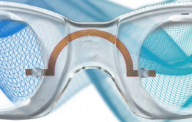
0.00 of 0 votesOptician in a Box - Revolutionizing Eyewear Access An estimated 1.6 billion people worldwide are unable to work due to the inability to afford spectacles. Kent Precision was tasked with designing a cost-effective, adjustable eyewear solution that could be easily customized to the individual user, particularly in developing countries where access to eyewear is limited. Design and Innovation The challenge was to create spectacles that could be adjusted in seconds to fit the user's facial features. The solution involved designing adjustable arms that provide up to 80mm of movement, multiple bridge sizes, and various frame widths. This enables the glasses to be quickly dispensed (within 10 minutes) and adapted to suit a wide range of users. Collaboration and Prototyping In collaboration with Style Eyes, Kent Precision utilized 3D printing to create initial prototypes. We gathered data on facial features to ensure the design would work universally across different individuals. SolidWorks was used to create detailed drawings and visualizations, with graphics added to the components to simulate the final product. Tool Making, Design, and Consultation Through tool making design and consultation, Kent Precision provided expert advice and support at every stage. We then created a prototype tool that allowed us to produce several units for BSI testing, which was essential for achieving certification as a Class 1 medical device. During this phase, we also suggested the addition of a UV stabilizer and a blue additive to ensure compliance with BSI standards and improve the durability of the product. In-House Production Tooling Once the prototype passed testing, production tooling was manufactured in-house by our expert toolmakers to support large-scale orders. This ensured that we could meet future demand while maintaining the quality and precision required for the medical device certification. Future Developments and Features As the project progresses, future developments include: Printed frames for further customization Laser-engraved markings on the frames and arms for identification and branding 3D-printed future concepts to explore new designs and features